
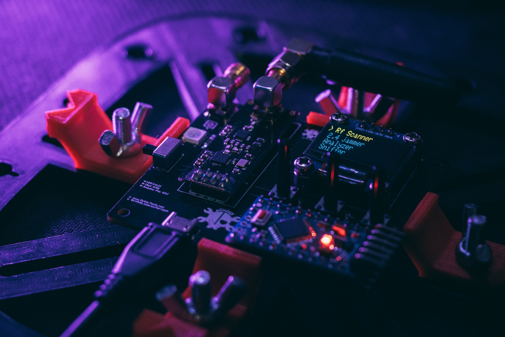
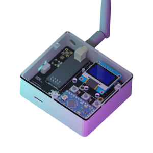
In this tutorial, we will go through the process of building a 2.4GHz scanner/jammer/Channel Analyzer named nRF-BOX using the nRF24L01 and Arduino Pro Mini. The nRF-BOX is a powerful tool to analyze and manipulate the 2.4GHz wireless spectrum. It allows us to scan the 2.4GHz band, jam the 2.4GHz band, and analyze the channels in the 2.4GHz band. The OLED 0.96 SSD1306 display will be used to show the menu and desired options.
🌟 About the Project
In this project, I build a 2.4GHz scanner/jammer/Channel Analyzer using the nRF24L01. nRF-BOX is a project that utilizes the capabilities of the nrf24 and Arduino mini to provide several functions such as an Rf scanner, 2.4Ghz jammer, and Rf Analyzer. The purpose of this tutorial is to explain the components, wiring, and programming involved in building the nRF-BOX project.
🎯 Features
- – Scan 2.4Ghz band
- – 2.4Ghz jammer
- – Channel Analyzer
🧰 Getting Started
We will use Arduino Pro Mini as a processor. Also, an OLED display to show the Menu and desired options. With the nRF24 module, we can execute the features.
To build the nRF-BOX, you will need the following components:
- • Arduino Pro Mini
- • nRF24L01
- • OLED 0.96 SSD1306
- • Connecting wires
- • Breadboard (optional)
🔌 Schematic
The connections between the components can be made according to the following table and schematic:
• Arduino and nRF24:
| Arduino and nRF24 | |
|---|---|
| Arduino | nRF24 |
| 9 | CE |
| 13 | SCK |
| 12 | MISO |
| 10 | CSN |
| 11 | MOSI |
| 3V3 | Vcc |
| GND | GND |
• Arduino and OLED display:
| Arduino and OLED display | |
|---|---|
| Arduino | OLED 0.96 |
| A5 | SCK |
| A4 | SDA |
| Vin | VDD |
| GND | GND |
⚙️ Installation
Before uploading the code, you need to install the following libraries in the Arduino IDE:
- • Adafruit SSD1306
- • GFX
- • NRF24
To install the libraries, follow these steps:
- 1. Open the Arduino IDE.
- 2 .Go to Sketch > Include Library > Manage Libraries.
- 3. Search for the “Adafruit SSD1306” library and install it.
- 4. Search for the “GFX” library and install it.
- 5. Search for the “NRF24” library and install it.
![]()
Code
If you’re interested in building this project on your own, the code is available on GitHub. Simply go to the GitHub repository, and download the code.
GitHub repository: https://github.com/cifertech/nRFBox
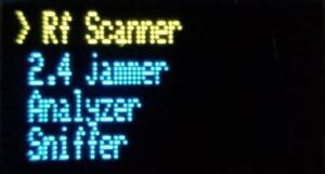
Once the libraries have been installed, you can upload the code to the Arduino Pro Mini. The code can be found in the accompanying source files. After uploading the code, the menu will appear on the OLED display, and you can choose the desired option.
👀 Usage
The nRF-BOX has three main options: Scan 2.4Ghz band, 2.4Ghz jammer, and Channel Analyzer. Each option can be selected from the menu by using the buttons on the nRF-BOX.
- • Scan 2.4Ghz band:
The Scan 2.4Ghz band option allows you to scan the entire 2.4Ghz band and see which channels are occupied. You can use this option to find the best channel for your wireless devices.
- • 2.4Ghz jammer:
The 2.4Ghz jammer option allows you to jam the 2.4Ghz band by transmitting noise on all the channels. This option is useful for testing the robustness of your wireless devices.
- • Channel Analyzer:
The Channel Analyzer option allows you to analyze the channels in the 2.4Ghz band and see how much activity is happening on each channel. This option is useful for finding the best channel for your wireless devices.
Conclusion:
In this tutorial, we have gone through the process of building a 2.4GHz scanner/jammer/Channel Analyzer using the nRF24L01 and an Arduino Pro Mini as the processor. We have also discussed the necessary components and the steps required to install the required libraries. Finally, we have covered the three main features of the nRF-BOX project, providing a comprehensive overview of the project.