
In this project, we will build a 2.4GHz Wlan scanner using the nRF24L01 radio board. In this project, the output delivers all the interference and information in the scanned area in the form of ASCII codes. In the project of making this scanner, we will use Arduino Nano as a processor. In the second part of this project, we will add an OLED display and display the scanned values in graphs and graphs. With the nRF24 module, we can scan and view the entire 2.4GHz network. This helps us to check the status of the signals in the network. Visit CiferTech for more tutorials, and be sure to follow my Instagram page to support me. ^-^
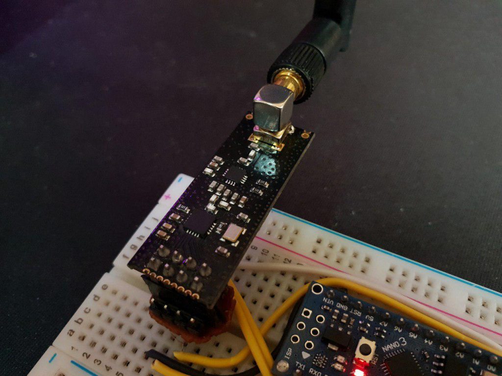
nRF24L01
This module is a transceiver, meaning it does both send and receive. These modules are very cheap on price with small size, the operating voltage of this module is from 1.9 to 3.6 volts, MOSI, MISO and SCK pins are the SPI pins of the module. Must be connected to SPI protocol pins in Arduino. The CSN and CE pins are for setting the module to active mode and switching between command mode and data transfer. These two pins can be attached to any digital pin on the Arduino. The IRQ pin is an interrupt pin and does not need to be connected.
Some of the specifications of these modules are as follows:
- Power consumption when sending data is about 12 mA.
- Range, if used outdoors with antenna, can reach up to 1000 meters
- Each module can communicate with up to 6 other modules.
- Use the 2.4 GHz band.
- You can send 1 to 25 bytes of raw data at a speed of 1 MB.
Interference in the 2.4 GHz network band
There are many devices that operate in the 2.4GHz range, such as; Telephone, Bluetooth, WiFi, car alarm, microwave are all in this range that with this project we will be able to measure and display these values. It is not usually very difficult to find interference. Products are coming to market that act as spectrum analyzers and use a standard USB interface to a laptop, meaning that the interference source can be easily used with an antenna to find interference.
Oled 0.96 SSD1306
OLED displays are commonly used in IoT and other embedded projects to display text and different amounts. These modules come in a variety of sizes depending on the type of the driver, one of the most popular being the SSD1306 These types of OLEds are usually made in 0.96 and 1.3 inch sizes. Also, the OLED communication protocol is I2C. The light emitting diode (OLED) display that we will use in this tutorial is the SSD1306, a 0.96-inch monochrome display with 128.64 pixels as shown in the figure below. The OLED display does not require backlighting, which results in a very good contrast in dark environments. Also, its pixels consume energy only when turned on, so the OLED screen consumes less power than other monitors.
Arduino
The Arduino board series is one of the most popular development boards among embedded engineers, which can be provided in various models such as Micro, proMini, Nano, Uno, as well as Mega, the core of these popular boards is the AtMega328 series. Arduino is an open source hardware and software platform. As mentioned earlier, the Arduino platform includes an open source single-control microcontroller that forms part of the Arduino hardware. In addition, the Arduino platform includes an Arduino IDE software designed to program for Arduino boards and a software bootloader that loads on the microcontroller.
Project working method
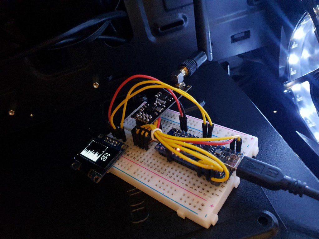
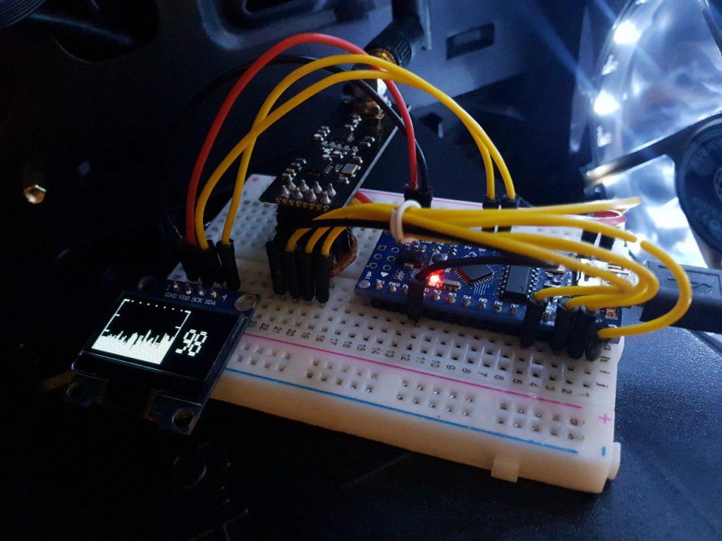
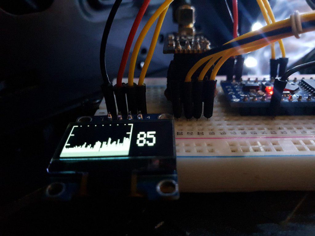
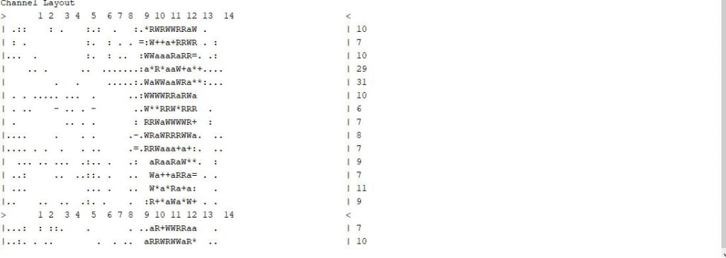
The activity of the nRF24 RF radio board is transmitted to the Arduino board via the serial interface and displays any type of activity in ASCII code. Domains are displayed in different channels with the help of a simple mapping. In this project, the 2.4GHz network scanner even shows the interference of microwaves and wireless cameras. Of course, you may be wondering what is the difference between this scanner and packet monitors ?! In response, I have to mention that in the monitor pack, it only monitors the 14 channels available for WiFi networks, but in this project, we can detect and actually see any frequency in the 2.4 range. In the second part, we will deal with this issue more. In the following, we will display these values in the form of graphs using the OLED display. The graph values are based on the nRF power consumption at the moment of scanning, which in this scenario is directly related to the input data.
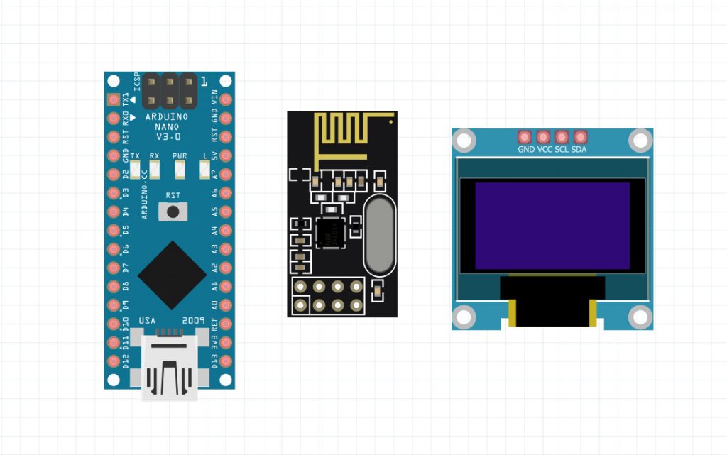
Items needed
- Arduino
- NRF24L01
- Oled 0.96
Library installation required
First, we will install the required library in Arduino IDE software. Follow these steps:
- Follow this path Sketch> Include Library> Manage Libraries
- Search for Adafruit SSD1306.
- Install the library.
- Then search for the word “GFX” and install it.
Connections and setup
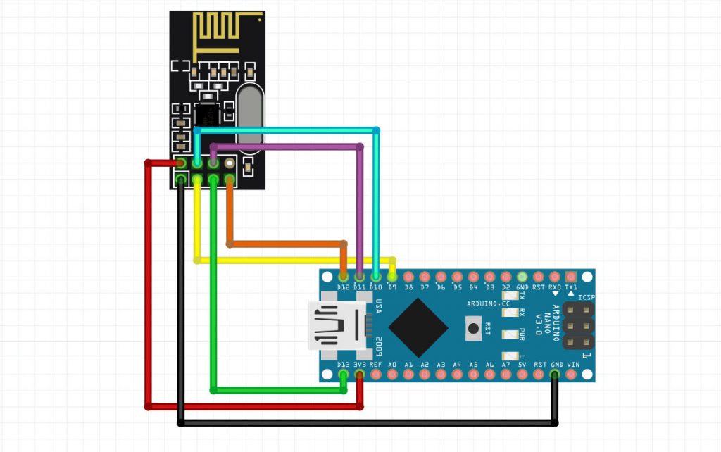
To start this project, we will first make the connections between the nRF24 module and the Arduino. Use the table and schematic below to make the connections.
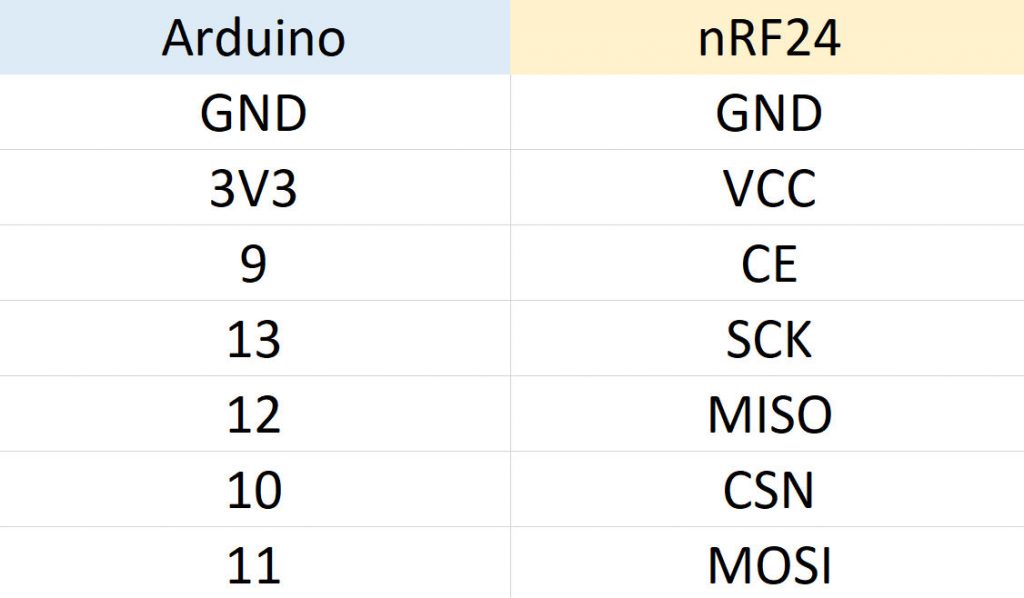
- Schematic of a 2.4GHz network scanner project using nRF24L01
In this step we will examine the important parts of the code that need to be explained. In the first part, we will call the required library.
|
1 |
<span style="font-size: 14px;">#include <SPI.h></span> |
In this section we will specify the display scale of the values called the gray scale.
|
1 |
<span style="font-size: 14px;">char grey[] = " .:-=+*aRW";</span> |
In this section we will set up the settings related to the SPI protocol.
|
1 2 3 4 |
<span style="font-size: 14px;"> SPI.begin(); SPI.setDataMode(SPI_MODE0); SPI.setClockDivider(SPI_CLOCK_DIV2); SPI.setBitOrder(MSBFIRST);</span> |
This section is about scanning all values in the 2.4GHz band.
|
1 2 3 4 5 6 7 8 9 10 11 12 13 14 15 16 17 18 19 20 |
<span style="font-size: 14px;">void scanChannels(void) { disable(); for( int j=0 ; j<200 ; j++) { for( int i=0 ; i<CHANNELS ; i++) { setRegister(_NRF24_RF_CH,(128*i)/CHANNELS); setRX(); delayMicroseconds(40); disable(); if( getRegister(_NRF24_RPD)>0 ) channel[i]++; } } }</span> |
In this section, we specify the values of the gray chart and then we will print these values in the monitor series.
|
1 2 3 4 5 6 7 8 9 |
<span style="font-size: 14px;"> if( norm!=0 ) pos = (channel[i]*10)/norm; else pos = 0; if( pos==0 && channel[i]>0 ) pos++; if( pos>9 ) pos = 9; Serial.print(grey[pos]); channel[i] = 0;</span> |
2.4 GHz network scanner project code using nRF24L01
|
1 2 3 4 5 6 7 8 9 10 11 12 13 14 15 16 17 18 19 20 21 22 23 24 25 26 27 28 29 30 31 32 33 34 35 36 37 38 39 40 41 42 43 44 45 46 47 48 49 50 51 52 53 54 55 56 57 58 59 60 61 62 63 64 65 66 67 68 69 70 71 72 73 74 75 76 77 78 79 80 81 82 83 84 85 86 87 88 89 90 91 92 93 94 95 96 97 98 99 100 101 102 103 104 105 106 107 108 109 110 111 112 113 114 115 116 117 118 119 120 121 122 123 124 125 126 127 128 129 130 131 132 133 134 135 136 137 138 139 140 141 142 143 144 145 146 147 148 149 150 151 152 153 154 155 156 157 158 159 160 161 162 |
<span style="font-size: 14px;">#include <SPI.h> #define CE 9 #define CHANNELS 64 int channel[CHANNELS]; int line; char grey[] = " .:-=+*aRW"; // nRF24L01P registers we need #define _NRF24_CONFIG 0x00 #define _NRF24_EN_AA 0x01 #define _NRF24_RF_CH 0x05 #define _NRF24_RF_SETUP 0x06 #define _NRF24_RPD 0x09 byte getRegister(byte r) { byte c; PORTB &=~_BV(2); c = SPI.transfer(r&0x1F); c = SPI.transfer(0); PORTB |= _BV(2); return(c); } void setRegister(byte r, byte v) { PORTB &=~_BV(2); SPI.transfer((r&0x1F)|0x20); SPI.transfer(v); PORTB |= _BV(2); } void powerUp(void) { setRegister(_NRF24_CONFIG,getRegister(_NRF24_CONFIG)|0x02); delayMicroseconds(130); } void powerDown(void) { setRegister(_NRF24_CONFIG,getRegister(_NRF24_CONFIG)&~0x02); } void enable(void) { PORTB |= _BV(1); } void disable(void) { PORTB &=~_BV(1); } void setRX(void) { setRegister(_NRF24_CONFIG,getRegister(_NRF24_CONFIG)|0x01); enable(); // this is slightly shorter than // the recommended delay of 130 usec // - but it works for me and speeds things up a little... delayMicroseconds(100); } void scanChannels(void) { disable(); for( int j=0 ; j<200 ; j++) { for( int i=0 ; i<CHANNELS ; i++) { setRegister(_NRF24_RF_CH,(128*i)/CHANNELS); setRX(); delayMicroseconds(40); disable(); if( getRegister(_NRF24_RPD)>0 ) channel[i]++; } } } void outputChannels(void) { int norm = 0; for( int i=0 ; i<CHANNELS ; i++) if( channel[i]>norm ) norm = channel[i]; Serial.print('|'); for( int i=0 ; i<CHANNELS ; i++) { int pos; if( norm!=0 ) pos = (channel[i]*10)/norm; else pos = 0; if( pos==0 && channel[i]>0 ) pos++; if( pos>9 ) pos = 9; Serial.print(grey[pos]); channel[i] = 0; } Serial.print("| "); Serial.println(norm); } void printChannels(void) { Serial.println("> 1 2 3 4 5 6 7 8 9 10 11 12 13 14 <"); } void setup() { Serial.begin(57600); Serial.println("Starting 2.4GHz Scanner ..."); Serial.println(); Serial.println("Channel Layout"); printChannels(); // Setup SPI SPI.begin(); SPI.setDataMode(SPI_MODE0); SPI.setClockDivider(SPI_CLOCK_DIV2); SPI.setBitOrder(MSBFIRST); // Activate Chip Enable pinMode(CE,OUTPUT); disable(); powerUp(); setRegister(_NRF24_EN_AA,0x0); setRegister(_NRF24_RF_SETUP,0x0F); line = 0; } void loop() { scanChannels(); outputChannels(); if( line++>12 ) { printChannels(); line = 0; } } </span> |
Add an OLED screen
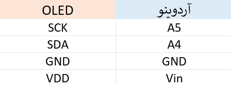
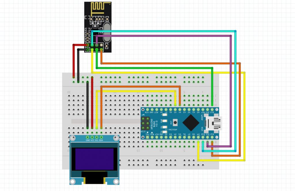
In the first step to start the project after installing the required libraries, we will establish connections between the nRF24 board, Arduino and OLED display. Make the connections according to the table and schematic below.
- Schematic of a 2.4GHz network scanner project using nRF24L01
In this step, we will upload the code on the Arduino Nano board, but first we will examine parts of the code. The following libraries were used in this code, their number increased compared to the previous tutorial which used only one library.
|
1 2 3 4 5 |
<span style="font-size: 14px;">#include <SPI.h> #include <Wire.h> #include <Adafruit_GFX.h> #include <Adafruit_SSD1306.h></span> |
This line of code contains an important part of the project, which defines the Gray symbol that represents the received data in the series.
|
1 2 |
<span style="font-size: 14px;">char grey[] = " .:-=+*aRW"; </span> |
In these few lines, several voids are defined in order, in the first case, we have set up the required registers.
|
1 2 3 4 5 6 7 |
<span style="font-size: 14px;">void setRegister(byte r, byte v) { PORTB &=~_BV(2); SPI.transfer((r&0x1F)|0x20); SPI.transfer(v); PORTB |= _BV(2); }</span> |
In this section we set the values displayed on the right side of Oled.
|
1 2 3 4 5 6 7 8 |
<span style="font-size: 14px;"> display.setCursor(90, 10); display.setTextSize(2); display.setTextColor(WHITE); display.print(norm); display.setCursor(90, 8); display.setTextSize(1); display.setTextColor(WHITE); display.print("");</span> |
Next, using the map, we equate the obtained values to the desired shapes.
|
1 2 |
<span style="font-size: 14px;"> drawHeight = map(norm, 0, 200, 0, 32 ); </span> |
Full code of 2.4 GHz network scanner project with nRF24L01 and OLED display
|
1 2 3 4 5 6 7 8 9 10 11 12 13 14 15 16 17 18 19 20 21 22 23 24 25 26 27 28 29 30 31 32 33 34 35 36 37 38 39 40 41 42 43 44 45 46 47 48 49 50 51 52 53 54 55 56 57 58 59 60 61 62 63 64 65 66 67 68 69 70 71 72 73 74 75 76 77 78 79 80 81 82 83 84 85 86 87 88 89 90 91 92 93 94 95 96 97 98 99 100 101 102 103 104 105 106 107 108 109 110 111 112 113 114 115 116 117 118 119 120 121 122 123 124 125 126 127 128 129 130 131 132 133 134 135 136 137 138 139 140 141 142 143 144 145 146 147 148 149 150 151 152 153 154 155 156 157 158 159 160 161 162 163 164 165 166 167 168 169 170 171 172 173 174 175 176 177 178 179 180 181 182 183 184 185 186 187 188 189 190 191 192 193 194 195 196 197 198 199 200 201 202 203 204 205 206 207 208 209 210 211 212 213 214 215 216 217 218 219 220 221 222 223 224 225 226 227 228 229 230 231 232 233 234 235 236 237 238 239 240 241 242 243 244 245 246 247 248 249 250 251 252 253 254 255 256 257 258 259 260 261 262 263 264 265 266 267 268 269 270 |
<span style="font-size: 14px;">#include <SPI.h> #include <Wire.h> #include <Adafruit_GFX.h> #include <Adafruit_SSD1306.h> #define OLED_RESET 4 #define CE 9 #define CHANNELS 64 int channel[CHANNELS]; int line; char grey[] = " .:-=+*aRW"; #define _NRF24_CONFIG 0x00 #define _NRF24_EN_AA 0x01 #define _NRF24_RF_CH 0x05 #define _NRF24_RF_SETUP 0x06 #define _NRF24_RPD 0x09 Adafruit_SSD1306 display = Adafruit_SSD1306(128, 32, &Wire); byte count; byte sensorArray[128]; byte drawHeight; char filled = 'F'; char drawDirection = 'R'; char slope = 'W'; byte getRegister(byte r) { byte c; PORTB &=~_BV(2); c = SPI.transfer(r&0x1F); c = SPI.transfer(0); PORTB |= _BV(2); return(c); } void setRegister(byte r, byte v) { PORTB &=~_BV(2); SPI.transfer((r&0x1F)|0x20); SPI.transfer(v); PORTB |= _BV(2); } void powerUp(void) { setRegister(_NRF24_CONFIG,getRegister(_NRF24_CONFIG)|0x02); delayMicroseconds(130); } void powerDown(void) { setRegister(_NRF24_CONFIG,getRegister(_NRF24_CONFIG)&~0x02); } void enable(void) { PORTB |= _BV(1); } void disable(void) { PORTB &=~_BV(1); } void setRX(void) { setRegister(_NRF24_CONFIG,getRegister(_NRF24_CONFIG)|0x01); enable(); delayMicroseconds(100); } void scanChannels(void) { disable(); for( int j=0 ; j<200 ; j++) { for( int i=0 ; i<CHANNELS ; i++) { setRegister(_NRF24_RF_CH,(128*i)/CHANNELS); setRX(); delayMicroseconds(40); disable(); if( getRegister(_NRF24_RPD)>0 ) channel[i]++; } } } void outputChannels(void) { int norm = 0; for( int i=0 ; i<CHANNELS ; i++) if( channel[i]>norm ) norm = channel[i]; Serial.print('|'); for( int i=0 ; i<CHANNELS ; i++) { int pos; if( norm!=0 ) pos = (channel[i]*10)/norm; else pos = 0; if( pos==0 && channel[i]>0 ) pos++; if( pos>9 ) pos = 9; Serial.print(grey[pos]); channel[i] = 0; } Serial.print("| "); Serial.println(norm); display.setCursor(90, 10); display.setTextSize(2); display.setTextColor(WHITE); display.print(norm); display.setCursor(90, 8); display.setTextSize(1); display.setTextColor(WHITE); display.print(""); display.drawLine(0, 0, 0, 32, WHITE); display.drawLine(80, 0, 80, 32, WHITE); for (count = 0; count < 40; count += 10) { display.drawLine(80, count, 75, count, WHITE); display.drawLine(0, count, 5, count, WHITE); } for (count = 10; count < 80; count += 10) { display.drawPixel(count, 0 , WHITE); display.drawPixel(count, 31 , WHITE); } drawHeight = map(norm, 0, 200, 0, 32 ); sensorArray[0] = drawHeight; for (count = 1; count <= 80; count++ ) { if (filled == 'D' || filled == 'd') { if (drawDirection == 'L' || drawDirection == 'l') { display.drawPixel(count, 32 - sensorArray[count - 1], WHITE); } else //else, draw dots from right to left { display.drawPixel(80 - count, 32 - sensorArray[count - 1], WHITE); } } else { if (drawDirection == 'L' || drawDirection == 'l') { if (slope == 'W' || slope == 'w') { display.drawLine(count, 32, count, 32 - sensorArray[count - 1], WHITE); } else { display.drawLine(count, 1, count, 32 - sensorArray[count - 1], WHITE); } } else { if (slope == 'W' || slope == 'w') { display.drawLine(80 - count, 32, 80 - count, 32 - sensorArray[count - 1], WHITE); } else { display.drawLine(80 - count, 1, 80 - count, 32 - sensorArray[count - 1], WHITE); } } } } // drawAxises(); display.display(); display.clearDisplay(); for (count = 80; count >= 2; count--) { sensorArray[count - 1] = sensorArray[count - 2]; } } void printChannels(void) { Serial.println("> 1 2 3 4 5 6 7 8 9 10 11 12 13 14 <"); } void setup() { Serial.begin(57600); display.begin(SSD1306_SWITCHCAPVCC, 0x3C); for (count = 0; count <= 128; count++) { sensorArray[count] = 0; } Serial.println("Starting 2.4GHz Scanner ..."); Serial.println(); Serial.println("Channel Layout"); printChannels(); SPI.begin(); SPI.setDataMode(SPI_MODE0); SPI.setClockDivider(SPI_CLOCK_DIV2); SPI.setBitOrder(MSBFIRST); pinMode(CE,OUTPUT); disable(); powerUp(); setRegister(_NRF24_EN_AA,0x0); setRegister(_NRF24_RF_SETUP,0x0F); } void loop() { scanChannels(); outputChannels(); if( line++>12 ) { printChannels(); line = 0; } } </span> |
Conclusion
In this project, using the nRF24 board as well as an Arduino nano, we built a scanner in the range of 2.4GHz networks, which is used in various projects. In the second part of the project, we analyzed the values and also displayed them graphically and graphically in We paid for the OLED display. You can use this project to scan existing network traffic over long distances, and also by analyzing the gray chart we can identify what source this information is and for what device.